Quantcast
Channel: Bentley Communities
Viewing all 357 articles
Browse latest View live

Did You Know? RAM Connection Shear Connections

$
0
0

Did You Know… RAM Connection has an extensive library of connection types built into the program? I frequently am asked, "Can RAM Connection do [     ]?" where the blank is filled in by a specific connection type.

This will be the first of two blogs providing an overview of connection types in RAM Connection. In today’s blog, I will cover shear connections. Moment connections and combined connections will be addressed in the next blog.

Most connection types in RAM Connection are available two ways:  Basic or Smart.  In the instance where a connection is only available as one type, I have noted it.  Otherwise, the connection is available as both types.

For a quick reference guide of connection types and their descriptions, download the attached PDF.

The following is a list of the majority of the shear connections available in RAM Connection.  This list was compiled for beam to column connections except where noted as a splice connection.  This is not an exhaustive list.  RAM Connection is customizable and it would be difficult to itemize every single connection available.

Shear Connections

1. Shear Plate

2. Through Plate (HSS) [Basic only]

3. End Plate Bolted

4. End Plate Welded

5. Double Angle All bolted

6. Double Angle All welded

7. Double Angle Welded to Support, Bolted to Beam

8. Double Angle Bolted to Support, Welded to Beam

9. Bent Plate Bolted (can also be welded) [Basic only]

10. Shear Tee All Bolted

11. Shear Tee All Welded

12. Shear Tee Bolted to Support, Welded to Beam

13. Shear Tee Welded to Support, Bolted to Beam

14. Stiffened Seated Angles

15. Stiffened Seated Plate

16. Stiffened Seated Tee Bolted [Smart only]

17. Stiffened Seated Tee Welded [Smart only]

18. Unstiffened Seated Bolted

19. Unstiffened Seated Welded

20. Column Splice Flange Plate Bolted [Basic only]

21. Column Splice Flange Plate Welded [Basic only]

22. Column Splice Shear Plate [Basic only]

23. Beam Splice Shear Plate

24. Beam Splice Double Angle [Smart only]


Did You Know? RAM Connection Moment Connections

$
0
0

Did You Know… RAM Connection has an extensive library of connection types built into the program? I frequently am asked, "Can RAM Connection do [ ]?" where the blank is filled in by a specific connection type.

This is the second of two blogs providing an overview of connection types in RAM Connection. In today’s blog, I will cover moment connections and combined connections. Shear connections were addressed in my previous blog.

Most connection types in RAM Connection are available two ways: Basic or Smart. In the instance where a connection is only available as one type, I have noted it. Otherwise, the connection is available as both types.

For a quick reference guide of connection types and their descriptions, download the attached PDF.

The following is a list of the majority of the moment and combined connections available in RAM Connection. This list was compiled for beam to column connections except where noted as a splice or cap connection. This is not an exhaustive list. RAM Connection is customizable and it would be difficult to itemize every single connection available.

Moment Connections 

1. Flange Plate Bolted

2. Flange Plate Welded

3. Moment Angle Bolted

4. Directly Welded [Smart only]

5. Cap Plate

6. Beam Splice Flange Plate Bolted [Basic only]

7. Beam Splice Flange Plate Welded

Combined Moment and Shear Connections

8. Moment End Plate Extended Both Ways

9. Moment End Plate Flush

10. Moment End Plate Extended One Way (up or down)

11. Moment End Plate HSS [Smart only]

12. Beam Splice with Moment End Plate Flush

13. Beam Splice with Moment End Plate Extended One Way (up or down)

14. Beam Splice with Moment End Plate at Apex

15. Beam Splice with Moment End Plate at Apex Extended Upwards

16. Moment End Plate Knee Vertical

17. Moment End Plate Knee Horizontal

18. Moment End Plate Knee Perpendicular

19. Column Splice Flange Plate Shear Plate Bolted

20. Beam Splice Flange Plate Shear Plate Bolted [Basic only]


Offsets in RAM Structural System

$
0
0

One of the newest features in RSS is Offsets and Rigid Links.  This feature has been in RSS since last year but is not being widely used.  Hopefully the Inside OUT of Offsets will give you the confidence to jump in and use them in your analysis.  (Based on RSS v14.05.03)

Probably more widely thought of  in concrete construction the Offsets command works for  Beams and Columns of material type Steel, Concrete, and Other.  It is also available for Beams designated as Smart Beams.  (Offsets are not available for Steel Joists or Walls.)

Offset Command - How it works

With your framing drawn in a traditional manner- columns on grid lines with beams framing between- specify a distance to move the beam or column and then select the member. 


Offset Command - Behind the scenes

Your member was moved in plan and RSS assigned a rigid link connecting the end of the beam with the center of the column. 


What is a Rigid Link?

Whether you Google the term or have learned it in a structural analysis course, a Rigid Link is a infinitely stiff element that connects two nodes.  Curiously enough this term is common in FEA analysis and in General FEA programs.  RSS uses a rigid link in the same way a general analysis FEA software (RE, STAAD, competitors) would. 

The Rigid Link connects two nodes that are non-coincident.  Preventing unsupported beam errors and free standing column errors (under one-way deck).  Allowing load transfer between elements and calculation of additional moments due to the eccentricity from the center of the members.


Free Form Offset Modeling - How it works

If you prefer to draw the structure in the actual location, ie starting out with unsupported beams, offsets are still possible by manually assigning the rigid links.

With the framing already drawn, select the rigid link command.  Select the end of the beam (or center of the column) and then select the center of the supporting column.


How does this affect my analysis?

In the years before the offset command, as engineers we rationalized the resulting moments from any offsets are small enough to be insignificant.  Depending on geometry these extra moments can be large.  Using the offset command will ensure you capture these additional forces.


Are there any integration advantages to using Offsets in RSS?

Offsets are fully supported in ISM and are maintained in Revit and AECOsim.  This allows accurate representation of the model in both the BIM  realm and the Analysis realm.


Watch Offsets in action as I assign, analyze, review, and integrate.

(Please visit the site to view this media)


Idiosyncrasies

As with any new tool there are some quirks that we need to get used to. 

  • If the edge of slab was defined as an offset from the member it will move with the member Offset.
  • If you want to change or remove the offset it's easier to delete the member and re-frame.
  • Offsets/Rigid links are assigned to the top of the column on plan only.


Don't let projects get you overstressed, RAM gives you strength. 


amgh

Useful View Toolbar Commands

$
0
0

Hello everyone!

Today I am writing about some useful features on the View toolbar that many people do not know about.  Or maybe you know these options are available but you don't ever use them.  When AutoPIPE is opened, the View Toolbar is located on the left side of the screen.  It is a floating toolbar, so the user can choose to move it from the left side of the screen and place it anywhere within the modeling area, by simply grabbing the top of the toolbar. 

This toolbar includes buttons for the most common view tools, such as zoom, pan, rotate and common view angles.  It also has some other very useful tools that are worth learning about.

Display Mode

There are three Display Mode buttons.  These buttons determine if the model is being represented as a Single Line, Wire-Frame or Solid Model.  The default setting is Single Line mode, but users may work in any mode and have the ability to switch between modes for best results.  The mode that is currently active will be indicated by the button looking like it is "pushed in" on the View Toolbar.


                                                    Single Line


                                                        Wire-Frame

                                                  Solid Model

The user has the option to change the number of wires represented when the Wire-Frame mode is chosen.  This option can be found under View --> Settings.  The user can change the number of wires to any number from 4 to 20 under "No. of Wires."


Viewports

There are also three viewports that the user can choose to view the model in.  The viewport buttons determine whether the modeling area is split up into one, two or four viewports based on the Single Viewport, Double Viewport and Quad Viewport options.  The viewport mode that is currently active will be indicated by the button looking like it is "pushed in" on the View Toolbar.  The different viewport options help the user to easily work in a view which is convenient and can be switched back and forth while modeling and/or viewing results.  To modify or use the View Toolbar common tools in a specific viewport, make sure to click on the viewport first so that it appears highlighted with a yellow box around it.


                                                     Single Viewport    


                                                   Double Viewport

                                                    Quad Viewport

Show Options

There are a lot of different Show Options directly on the View Toolbar.  These options include Show Pipe Properties, Temperature, Pressure, Additional Weights, Concentrated Forces, Imposed Displacements, Thermal Anchor Movements, Valve Data, Flange Data, Tee Data, Soil Properties, Length, Reference Points and Joint Type and User SIF Data.  The Show Pipe Properties button brings up a dialog box to choose between graphically viewing the model by Pipe Daimeter, Schedule, Wall Thickness, Pipe Material, Pipe Identifier, etc,  The View Toolbar also includes a Show Reset button that can be used to reset all of the options selected to the default settings.  While going to View --> Show Options allows the user to access even more show options, it is helpful to know that these common option buttons are available with one simple click.  Hover over the buttons in the area of the Show Options on the View Toolbar to understand what each button shows in the model.


                                                   Show Temperature                                              


                                   Show Valve, Flange & Tee Data      


                                                          Show Length    

The Show Options button on the bottom right of the View Toolbar opens up the Show Options Dialog box, which can also be accessed by View --> Show Options...  This dialog box provides all of the different options to plot data and components in the model.  The user can choose to plot Pipe, Structure and Support Properties, Component Data, Xtra Data and Color Plots and also Show Connected Segments here.  The user can also Preview the updates to the model plot before accepting the changes.  This is a very useful dialog box, take the time to look at it and understand the options.


Measure Distance

The Measure Distance button acts as a graphical distance calculator.  It can be used to check distances and clearances between pipes and structures.  The user would select the Measure Distance button and then choose the FROM and TO points and click Calculate down on the Status Bar.  Remember that the Status arBar is in the lower left corner of the screen.  The user can choose the FROM and TO Points by clicking on points in the model with the mouse or typing in the name of the points.  The DX, DY and DZ Offsets and the straight-line distance will then be displayed in the Status Bar.  To stop using the Measure Distance tool, simply click Close  on the Status Bar.


Show Insulation

The Show Insulation button can be used to display the insulation on any piping in the model in a transparent color.  It does not give specific properties about the insulation, but simply shows which piping has insulation.  The color of the pipe insulation can be changed by going to Tools --> Settings --> Colors and choosing PipeInsulation.


I hope this information about the View Toolbar was useful to you!  There are many easily accessible options on the toolbars in AutoPIPE that are often overlooked or forgotten about.  Try to get used to using these tools, as the simple one-click button method will make your modeling and viewing results more efficient!

Thanks!

SS5 - DWT Creation (Best Practices)

$
0
0

PS V8i (SS5) – DWT Creation - Best Practices for AutoCAD

  Chapter One  

Before beginning to generate a model in ProStructures, many of the underlying settings should be in place. There are quite a few settings to consider but fortunately, most of these can be saved to a Drawing Template (DWT) and loaded each time a new model is to be created. It is the understanding throughout this post that you already know how to create and save an AutoCAD .DWT file.

Throughout this document we will look at some of the more relevant features and settings that can be added to the DWT. This is not meant as a feature by feature guide to all the settings available, nor is it meant as an absolute requirement to generating your models and drawings. What we will be looking at is settings that represent key features in generating good models.

Additionally this document has been divided into two areas due to the fact that the DWT used for generating 3D models and the one used for generating 2D drawings should be set up differently.

Now let’s begin by looking at some of the settings for the 3D modeling environment.

  Section 1.1 – 3D – The Global Options  


The ‘Global Options’ have many settings that handle all kinds of functions throughout the ProStructures program. It is not my intent here to cover each and every setting but simply to point out some of the key settings that you may wish to take note of.

First of all let’s look at how we access the Global Options. With ProStructures loaded there are two ways to open up the Global Options dialog window, first you can go from the dropdown menu that is available in AutoCAD (Though not always enabled) by going to “ProStructures à ProSteel Options”.

The second method is to have nothing selected and right click in the model space area and from the menu that appears select “ProSteel à Options”.

 Both methods will open up the Global Options dialog window. From this dialog we have access to many of the global features available in ProStructures and we will be focusing on a couple of key features for this document.

-=-=-=-=-=-=-


First let’s begin with the ‘Options’ area.

The first settings we should look at are the “Remove” settings. Note that there are three settings that begin with the word remove. Each of these settings attaches to the purge command when enabled and allows the user to purge out not only the standard
AutoCAD entities but also the ProStructures specific entities.

Immediately following these options is the Check DWG during load. This is an important setting as it will check the drawing for errors whenever it is loaded. For this function properly however the “Proxygraphics” must be disabled (Set to ‘0’).
Proxy graphics is an AutoCAD command so you can simply type this into the command line to change the setting. Another bonus to having the Proxygraphics disabled (Set to ‘0’) is that the file sizes can be up to ten times smaller.
This also gets saved with the DWT (Drawing Template).

Lastly, turn on the ‘Convert Boolean’ and ‘Execute Boolean First’. The simple explanation for this is that it will allow you to open and manipulate much larger files if these settings are enabled.

-=-=-=-=-=-=-

The next setting I’d like to mention is the “Length always largest value” setting under the ‘Straight Plates --> Plate Description’ area. Please ensure that this option is not enabled as, depending on how a plate is drawn, it may cause the values of your BOM to be displayed incorrectly.

Leave this setting ‘Unchecked’.

-=-=-=-=-=-=-

Another important setting is the Actual Geometry’ setting found in the ‘Straight Plates --> Calculation Method’ area.

The ‘Calculation Method’ setting from the dropdown box will affect the weights listed in you BOMs. For actual weights set this to ‘Actual Geometry’. If you are doing fabrication and want to include the weight of the wasted material you may want
to change this to ‘Extents’.

-=-=-=-=-=-=-

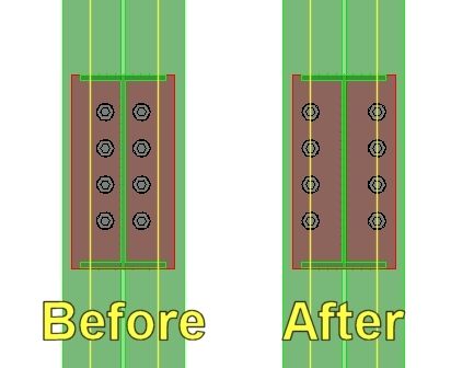
In the Bolts Section You may want to ensure that the “Enable Back to Back Bolting” is enabled.


If you are connecting beams using clip angles as an example and these beams go to either side of a supporting members web then this will recognize that the holes line up and handle the bolts used in this situation correctly.

-=-=-=-=-=-=-

 In the ‘Values’ section of the ‘Global Options’ you will find two settings, one for ‘Front Distance’ and the other for ‘Back Distance’.

These settings will control your default clipping plane distances which in turn will also affect all of your viewtools that cause clipping planes to be enabled.

-=-=-=-=-=-=-

Passive and Active Logical Links should be enabled (Checked).
These settings allow your model to dynamically react to changes once things like coping or connections have been put into place. Set the Update dropdown boxes to Automatically.

You may also wish to enable the ‘Allow Additional Data’ option if you intend to call out Connection details. This will enable and additional tab when connections are being placed that allows the user to add in a description and identifier. If
these fields have values then you will be able to call the connection in as a detail during the 2D drawing production phase.

-=-=-=-=-=-=- 

Three important settings in the 'Display Area'.

First the paperspace viewport options should be set to ‘Without Support’ while modeling and only enabled once the model is done and the 2D drawing generation begins.

Also you may wish to ensure that the ‘Shape and Plate Clipping’ options are enabled. This will allow the program to display the cross section of shapes when looked at from the center area where the clipping depth does not reach the end of the member.

Lastly ‘Do not display Part Labels’ should be disabled (Unchecked) or else all labels everywhere will be hidden regardless of any other setting.

-=-=-=-=-=-=- 

The settings for the 'Dialog settings' area are usually set as follows:

“Use CAD System settings” in all three instances as enabled (Checked). This then retrieves the values used from AutoCAD that were set up when ‘UNITS’ is typed at the command line. Units should always be set regardless and here the user has the ability
to call those settings in.

“Expert Mode” is typically set to “Beginner”. Changing this setting, especially to Expert mode may provide additional settings in different areas but the user then loses the ability to use the graphical reference at the right side of the dialog windows while working.  If the extra features are needed it is recommended that the user come into the Global Options, switch to ‘Expert’ mode to use these features and when done change back to ‘Beginner’ mode. For the sake of the DWT, leave this setting to ‘Beginner’.

-=-=-=-=-=-=-

 At this point you may wish to generate a template for your settings so that if they are ever lost for whatever reason calling them back will be easy with the template in place.

Again, please note that this is not an exhaustive list of features and settings but rather some of the highlighted ones that may prove useful. A good suggestion is to start with the provided drawing templates that come with ProStructures. For North America this is typically the “PS-S#-US-CDN_Imp” or “PS-S#-US-CDN_Met” as these drawing templates have many of the best settings already in place.

  Section 1.2 – 3D – Additional Items to Consider  

In addition to the settings mentioned in the first part you may also want to consider setting up and including the following items. 

  • ‘Proxygraphics’ should be off (Set to ‘0’). You can type this command at the command line.
  • ‘Units’ should be set properly. You can type this command at the command line.
  • Your AutoCAD dimension styles
  • Your AutoCAD text styles
  • Display and Area Classes from within ProStructures (Optional)
  • Part Families from within ProStructures (Optional)
  • Global Options (above) set properly.


  Chapter Two  

  Section 2.1 – 2D – Drawing Template for 2D Detailing  

When it comes to developing a ‘Drawing Template’ for 2D drawing creation, this should be a separate file from the 3D drawing template. In the case of setting up a 2D environment you do not want to include anything except what is absolutely necessary. For example, you may have a border/’title block’ included in the file but then only the text styles used with this border should be included and nothing else. 

The reason for using a clean file for the 2D drawing is that when 2D drawings are generated through ProStructures, all of the necessary files are brought over from the models environment. To avoid conflicts or errors it is best to leave the 2D drawing template as empty as possible so that it is ready to receive everything from the models environment.

 As stated in the training manual for this product, “ For 2D drawing generation, ProStructures takes all required text and dimension styles specified in the Detailstyle from the model and brings them over to the 2D drawing.”


   Chapter Three  

  Section 3.1 – Additional Information  

The document can be found online here:

http://communities.bentley.com/products/structural/drafting___detailing/m/drafting_and_detailing_gallery/249464.aspx

News: First ProConcrete training has been delivered

$
0
0

I want to share with you my experience with delivering our first ProConcrete onsite training. It was delivered last week in Hopkins, MN (Suburb of Minneapolis/St. Paul).

The standard ProConcrete training is 2½ days (20 hours). It could be 2 days (16 hours) if the people being trained already have ProSteel experience since some tools are common to ProSteel & ProConcrete. In this case it was a new user that had never used either software.

We had scheduled 4½ days at the client's offices using 2½ days for training and 2 days for coaching.

The training went fine from Monday to Wednesday a little after mid-day. The client has some very specific type of structures they build and needed a more personal approach on how to model the structures they normally build. Because of this, we took a bit of time out of the coaching part to accommodate the training.

The coaching part was intended so that the users could use their knowledge during training to build something that resembles more of what they really do and have the instructor around to help and answer any questions. The reason for this is that the training was to be delivered using the exercises prepared in our manual which did not necessarily reflect what the client produces in real life. The manual is intended to show how to use the commands in a general way so the users have the knowledge of what the software can do, not necessarily showing what they do in a day to day basis.

Since this was the 1st training delivered for ProConcrete in North America, using a new manual and dataset, some comments and propositions from the users that attended this training will be looked at in order to make the training material better.

The general feedback from the users present was positive. There is a return trip to be schedule with this client in order to pursue the coaching and possibly revise some of the topics covered in the training later this fall.


On another note, I'd like to thank the Air Canada crew for their superb job handling the uncontrollable circumstances that occurred during my return trip on Friday after the class was over. As you might have heard, there was a major thunder storm in the North East area which closed my connecting airport (Toronto's Pearson International, a.k.a YYZ) for a few hours and also closed my home town airport (Montreal's Pierre-Elliot-Trudeau International, a.k.a YUL).

My trip started a 1:00pm at Minneapolis-Saint Paul International (a.k.a. MSP), once in the air, about 45mins before scheduled time to arrival at YYZ, the captain came on air to announce that YYZ was shut down, we were to be redirected to North Bay (not an international airport...meaning no customs). So we landed there, and because there is no customs at that airport, we had to stay on the tarmac, inside the plane, for 4 hours, until Pearson re-opened. During this time we had no food, and no more water bottles were available on the plane since this flight was schedule to be only 2¼ hours long.

The captain was about to take it upon himself to allow us to de-board the plane (this is a procedure normally used in private planes, but can be applied in special circumstances) when the air traffic controller came on to let us know we were cleared to take off and head back to YYZ. We landed there at 10:45pm

Needless to say, by the time we reached YYZ, my connecting flight to YUL should have been gone. Well no it wasn't. It was also delayed because of the closure of both airports I had to fly to (YYZ & YUL). This flight was supposed to leave YYZ at 8:30pm, but was delayed and only departed at midnight. Giving me time to clear customs and find my gate.

I finally arrived home 13 hours after I arrived to MSP airport. But the trip was pleasant thanks to a superb crew who did all they could to make us comfortable.

Did You Know? RAM Elements for Concrete Design & Detailing

$
0
0

When using RAM Elements for concrete structures, did you know that there are multiple ways to have the program perform design and detailing functions?  Method #1 uses design options from directly within your 2D/3D model.  Method #2 uses design and detailing options located in the Modules.

Let’s take a look at a sample concrete structure and review the design and detailing options available.

Our model is a two story structure with lateral concrete frames at the upper story and concrete shear walls at the lower story.  The walls have integrated concrete pilasters that continue down from the columns above.  I’ve modeled a two-way concrete slab to distribute the surface dead and live loads.  For lateral loads, I’ve modeled equivalent wind point loads in the X direction as well as pressure component loads on the walls in the X direction.  For scale, the bays are 20 ft x 30 ft, and the stories are 12’-6” floor to floor.  The model has been analyzed and designed.


Method #1 – Slab, Wall, Beam, and Column Design within the 2D / 3D model


Slabs / Walls:  Select the View tab and the Stresses button.  For a concrete shell element, you may select AS1 or AS3 from the drop down menu to see a color-coded output of required area of flexural reinforcement in each of the principal directions, both top and bottom.  This will NOT choose the bars, only provide an area of steel.  Be sure to set your mechanical cover in your shells dialogue for correct output.


Beams / Columns:   Select the beams and columns for which you wish to obtain design results.  Then go to Output -> Design -> Reinforced Concrete.  Make your selections in the dialog box and click OK.  You will get a design report for each member’s required area of longitudinal steel and tie size and spacing.  This will NOT choose the bars, only provide an area of steel.For beams, axial forces and weak axis shear and moments are not considered.  For columns, torsion is ignored.


Method #2 –Wall, Beam, and Column Design within the Modules


Walls:  In the 3D model, select walls and columns in a single plane.  From the Modules tab, select the drop down menu to Asssign -> Concrete Wall.  The entire wall element with pilasters will be imported into the Concrete Wall Design Module.  Make your design selections for allowable bar sizes and spacing, and click Optimize.  The program will choose bar layout for the walls and columns, which may be viewed on the Detailing tab.


Beams:  In the 3D model, select beams in a horizontal line.  From the Modules tab, select the drop down menu for Beams -> Concrete.  The entire beam line, including support information, will be imported into the Concrete Beam Design Module.  Make your design selections for allowable bar sizes and spacing, and click Optimize.  The program will choose bar layout for the beams, which may be viewed on the Detailing tab.


Columns:  In the 3D model, select columns in a single vertical line.  From the Modules tab, select the Concrete Columns button.  The entire column line, including supported beam information, will be imported into the Concrete Column Design Module.  Make your design selections for allowable bar sizes and spacing, and click Optimize.  The program will choose bar layout for the columns, which may be viewed on the Detailing tab.


Now that you know about RAM Elements’ concrete design and detailing options, be sure to put them to use with your next concrete structure!


NEWS: SS6 Release and AutoCAD 2014 Support

$
0
0


In case you haven't heard, here are a couple of things that have been announced lately.

  • The SS6 version of ProStructures will soon be released. 
  • AutoCAD 2014 support is now available.
  • Information about the Migration Assitant, the Archiving Assistant and Enhanced Section and Material Mapping for ISM is now available.
  • There is a new standard stair utility being released.


You can find more information about these here:

http://communities.bentley.com/products/structural/drafting___detailing/w/structural_drafting_and_detailing__wiki/7116.aspx


To create a Saved View from New or Existing Callouts within a Sheet Model

$
0
0

Imagine a scenario where you are working on the front view of a 3D model for a house. You are required to produce a top-view of the foundation for this 3D model. Using the Detailing Symbols tools a callout can be placed along the line of the foundation in the front view that generates the desired dynamic view. The position of the callout can be modified to dynamically change the position of this view.  Once this dynamic view has been generated you may find it of interest to learn about the origins of their attributes.

A series of blogs has been produced that will aid you in the construction of dynamic views using common scenarios. These should provide you with an insight as to where the Saved View attributes have been inherited.

Follow these steps to create a new dynamic view on a sheet model:

  1. Open an existing design file containing a 3D design model.
  2. Go to Tools > Detailing Symbols > Place Section Callout.
  3. Select Drawing Seed. (see Drawing Seed blog)
  4. Select the Create Drawing check-box.
  5. Select the start, end and depth to place the Callout. The “Create Drawing” dialog will open.
  6. Select the “Create Drawing Model” and “Create Sheet Model” checkboxes to create a drawing and sheet model.
  7. Click OK. A new saved view and its drawing and sheet models will have been created.

Roof and Floor loading without the Roof or the Floor

$
0
0


 Roof and Floor loading without the Roof or the Floor  

In STAAD.Pro, there are many ways to properly account for loading to be distributed across the structural framing of roof and floor members. We will discuss some of the practical options for accurately assigning uniform pressure loads to roof and
floor members without modeling the slab or deck that distributes the loading to the structural members.


For this discussion we will focus on vertical loads due to gravity for Dead Load, Live Load, and Snow Load. There are a few considerations that we want to think about
before we begin the process of creating our roof and floor loads. The following are a few questions we can pose to help decide which STAAD.Pro loading tools which best suit the structural framing:


Do we have openings in sections of the floor or roof? Are portions of the framing system sloped? How is the uniform loading on the framing changing within each load case and also between separate load cases? What is the complexity of the structural member layout? Is the layout a simple rectangular bay system or are there curved members and variable member spacing?

The reason these questions are important for applying loading to the model is that the answers to these questions will help determine the most useful tools within STAAD.Pro to address the calculation, application, and automation of load distribution to our structural framing. Tools like floor beam groups and configurable floor loading make it possible to quickly calculate, apply, and adjust distributed loading to floor and roof systems.

Using floor beam groups will allow us to assign distributed loads to a set group of members without having to apply the load to the entire floor system. This tool works well in cases where loading varies across different portions of the floor or in a situation where the framing is sloped.


STAAD will automatically calculate the tributary area for the floor or roof member group
and apply the calculated uniform load as a one way or two load distribution based on your selection. Using the floor load command, you are able to apply a pressure load such as dead load due to a slab, or an assumed live load for roofs and floors, or a snow load to a group of members on a designated area of
the structural framing. For example this method works well for dead load due to
a slab, where the slab thickness and weight will be the same on multiple floors
however the framing layout or spacing will vary from floor to floor. Rather than manually calculating the tributary area for each member and assigning a uniform load on members one by one, the floor load can be designated to several floors at once and the uniform load for each member will be calculated automatically by STAAD.Pro based on the member tributary area.


It is necessary to fore warn you that not all floor configurations will allow STAAD.pro to automatically calculate the uniform load based on the member tributary area. Therefore, in complex structural framing situations it may be necessary to use multiple floor member groups or possibly even manually assign the uniform loads to members in order to accurately generate loads on the structure.


For single sloped roofs one floor group may be all that is required to assign the pressure loads to the structural framing. However for gable or hip roofs one floor member group will be required for each portion of the roof with an individual slope.


For additional information on floor loading in STAAD.Pro refer to the technical reference manual pages 5.32.4.3 Floor Load Specification. I hope that this information has been useful. Please feel free to email me with additional questions.

Thanks

Karimu.Rashad@Bentley.com

News: Insider Skills eSeminars

$
0
0

The 3rd Insider Skills FREE eSeminar for ProStructures has been delivered.

This was the 1st of these ProStructures eSeminars talking about ProConcrete. The topics covered were the placement of concrete & reinforcement.

If you missed the eSeminar (or want to see a past eSeminar), you can find them all (ProStructures, AutoPIPE, STAAD, RAM) on our YouTube channel here.

Here is a list of all the Insider Skills delivered up to date with link to their recording. 

#ProductDateTopicLinks to videos
1ProStructures June 7th 2013IntegrationPart 1 / Part 2
1AutoPIPEJune 14th 2013IntegrationPart 1
1STAADJune 21st 2013IntegrationPart 1
1RAMJune 28th 2013IntegrationPart 1
2ProStructuresJuly 5th 2013DetailCenterPart 1
2AutoPIPEJuly 12th 2013Top FeaturesPart 1
2STAADJuly 19th 2013Top TipsPart 1Part 2 / Part 3
2RAMJuly 26th 2013Efficiency TipsPart 1 / Part 2 / Part 3Part 4
 3ProStructuresAugust 2nd 2013Concrete & RebarPart 1 / Part 2 / Part 3


Here are the remaining eSeminars to come:

ProStructures :                 Sep 06 / Oct 04 / Nov 01 / Dec 06

         Autopipe : Aug 09 / Sep 13 / Oct 11 / Nov 08 / Dec 06

            STAAD: Aug 16 / Sep 20 / Oct 18 / Nov 15 / Dec 13

                RAM : Aug 23 / Sep 27 / Oct 25 / Nov 22 / Dec 13

They all take place on Friday's @ 1pm Eastern, 12pm Central, 11am Mountain, 10am Pacific

Click >here< to join any of these eSeminars at the appropriate time.

New Enhancements to AutoPIPE v9.6

$
0
0

Here is a list of new enhancements for AutoPIPE v9.6!


  • Rotate geometry, supports, local and global static loads
  • Add snow load option
  • Add Indian BHEL Spring Manufacturer
  • Add DNV 2012 piping code
  • Print Time history displacement results by time step
  • Add latest HDPE Stress Design and material library
  • Add time history modal results to MOD file
  • Add STAAD wind and seismic load generators
  • Add features to interface with LISEGA pipe support software
  • Add Wave visual aids
  • PCF import, tolerance to join disconnected elements
  • Pipelink: Manage multiple structures in pipelink
  • Add feature to batch process multiple PCF files into one DAT file
  • Add Ring Main Wizard to AutoPIPE
  • Import displacement data from Excel
  • Import coordinate data from Excel
  • Duplicate Operating cases
  • Add B31.1 2012 Edition
  • Add B31.4 2009 and 2012 piping code
  • Add B31.3 2012 piping code
  • Add PSS Spring Manufacturer (Germany / UK Vendor)
  • PCF Translator: Program should detect overlapping components
  • Add axis transformation for PXF Import and DGN Export
  • Add ASME B31.8 2012 piping code
  • B31.3-2010: Add functionality for user to enter axial and torsional SIF
  • Define and view load case description
  • Implement Trust Licensing
  • Implement feature tracking
  • PCF Translator: Add an option to ignore overlapping components
  • PCF Translator: Add support to define axis mapping between PCF and program
  • PCF Translator: Move Toler., flange length, Ignore options to Tools>Setting dlg
  • FlangeAnalysis: A new Menu Button option to filter out the non-code combinations
  • Add option to define spring variability
  • Update Water Hammer and Steam Relief Examples in Online Help
  • Improve the analyze time of ANSI Check Flange analysis

 Looking forward to the release of AutoPIPE v9.6 and AutoPIPE Vessel!

Modelación de Cámaras Rompe Presión

$
0
0

Hola amigos, saben como se puede modelar cámaras rompe presión en watercad?, lo he intentado con la herramienta "discharge to atmophere" pero no me funcionó. Muchas Gracias.

Did You Know? RAM Steel for Gerber Beam Systems

$
0
0

Did you know that you can model a Gerber beam system in RAM Steel?  A Gerber beam system is also known as a cantilever drop-in beam system or a cantilever girder system or cantilever span system.  (Or just about any combination of the words “cantilever,” “span,” “drop-in,” “beam,” and “girder” that your heart desires.)

A Gerber beam system can often be used to reduce beam sizes or beam depths in a floor system.  By cantilevering the girders over the column supports, one can take advantage of the negative moment capacity in the girders.

Our typical roof layout for this example is shown below.  The girders span 30’ between columns in the X direction with 3’-9” cantilevers (equal to 1/8th of the span).  Open web steel joists span 20’ between girders in the Y direction.  I’ve assumed a one-way metal deck span with non-composite beams.

To create the Gerber system, frame the girders from column to column where applicable.  Then, using the “Assign Cantilevers” command, add cantilevers to the girder ends where applicable.  Now you are able to frame the drop-in beams between the cantilever ends of the girders.

For this example, our model is loaded with self-weight, an additional dead load of 10 PSF, and roof live load of 50 PSF.  Let’s take a look at the sizes that RAM Steel chooses for the Gerber system.

Gerber System:

Did you know that RAM Steel internally skip loads the live load on cantilevered beams to produce the worst case positive and negative moment?  When loaded with positive live loads only, the following combinations are checked.  (See the RAM Steel manual for situations where both positive and negative live loads are applied.) 

  • Live Loads on Span and Both Cantilevers
  • Live Loads on Span only
  • Live Loads on Left Cantilever only
  • Live Loads on Left Cantilever and Span only
  • Live Loads on Right Cantilever and Span only
  • Live Loads on Right Cantilever only

For the W21x44 beam circled in red above, the six loadings yield the moment diagrams as illustrated in RAM Elements below.

You can see that these values match the maximum design moments in the RAM Steel report.

Just for fun, I also ran the design with a traditional single-span beam system.  The beam sizes which RAM Steel chose are in the picture below.


Single-Span System:

Reviewing the Material Takeoff report for this system shows us that the traditional single-span design actually yields a more efficient design.  This considers only main steel, of course, and does not include connections or ease of construction.  So in addition to providing design values for a Gerber system, RAM Steel can also help you choose between systems to minimize your steel weight and therefore your structural costs.


If you've ever wondered whether RAM can perform a certain task, please email me with your questions.  I'm always on the lookout for blog material which interests my readers.

Tip No.7: Automatically use bolting line on Endplate connection.

$
0
0

When using the Endplate connection,


if one of the steel elements is being connected to its flange (like the column in the example below).


it is possible to have the bolt line values (defined in the shape's database) used automatically to place the bolts.

Simply enter the letter "w" in the "Middle" field of horizontal distribution and ProSteel will automatically read the value from the database and place it in the field.


SS5 - Workframe using ALT Key-In

$
0
0

Adding Gridlines:


Setting up a large workframe can be cumbersome if many different bay sizes are required. Here's a quick way to go in and add in bay sizes that may save you some time and frustration.


To use the key-in method, Uncheck the evenly spaced option and open the dropdown box on the right.


With the dropdown open, hold the 'ALT' key and left click anywhere in the dropdown. This will bring up another dialog which will allow you to enter values for each line, separated by a comma.


The way this dialog window works is that each value entered represents one of the lines in the dropdown box. So the first value would be the first line of the dropdown, the second value would be the second line and so on in order.


If a series of equally spaced bays occur it is possible to type it in like this "4*10:0" without quotes. This will tell the system to generate 4 bays in a row at 10 feet each. Simply use a comma before and after this statement in the same way you would if you were entering a single value.


Removing the Gridlines: 

In addition to using the dropdown like usual and typing in a 0:0 value where needed, this method can also be used to reset the lines to 0:0 if needed. To remove all the bays simply open the alternate key-in dialog and type in a number greater than the amount of bays that exist times 0:0.  For example, if you had 49 bays you could open the Key-in dialog and type "50*0:0" and this would reset all the values to '0' and the bays would disappear.

 Keep in mind however that using this method will always start from the first value in the list and so if only specific values in the middle of the list should be removed then it might be easier to do it from the dropdown; unless all the values still appear in the key-in dialog when reopened, in wich case you could simply exchange the value listed with a 0.

SS5 - Isolate Tool

$
0
0

The Isolate tool is a tool that quietly slipped in since the release of Select Series 5. This tool has been added to the ProStructures task area under MicroStation and on the View Tools toolbar under AutoCAD.


The purpose of this tool is to help visualize a shape, sub-group, group or assembly by presenting it in 4 different views. With this the selected object is automatically taken and shown with a Front, Top, Left and Iso view.


Lets take a look at an example of how this works. In this example we start with a simple model.


With the model showing, select the type of Isolation you want to create from the toolset.


In this case we will look at the 'Isolate group' function.


Click the button and then the member included in the group and the results will be something like this.


There is also an option to show the selection with adjacent parts, if I were to select the group option with adjacent parts then the result would be similar to this.


Solids Working Area (or SWA)

$
0
0

Quite a bit has been said about the subject... some of it being true, some of it not being so true. To help "clear the air" about it...

The best practice for solids modeling in MicroStation is to keep it simple. If you consider a 3D model in a V8 DGN file to be a "universe", keep your model at the center of that "universe" (i.e. TRUE 0,0,0). When you do that, your results will be predictable and precise. If you want to create a 3D solids model that will be used as part of an "assembly" with other models, then take advantage of MicroStation's global origin and reference using the Coincident World attachment method. You should definitely NOT create models that are far away from the center of the "universe" and use the global origin to try to make the model look like it is at the center of the "universe".

So remember, "Stay close to 0,0,0, my friends".

SS5 - Search Tool

$
0
0

Search Tool (for ACAD based ProStructures version)

In this blog we are going to focus on a particular ProStructures tool called ‘Search Parts’. This search tool will allow you to manipulate what you see in your model in different ways.

For this example we will look at a model that would need to have its beam members modified. This will demonstrate a way by which these beam members can be segregated easily so that we can select and manipulate them.

This is only one example of what this tool can be used for and that many other applications of the tool can be implemented if needed.

To begin with it should be noted that the search tool will only find elements that are visible, so be sure that the model in question is present and all the elements are showing


1.1  – Search Tool Location

1.1.1 - Finding the Search Tool

Here we need to start the Search tool. This is done by going to the ProSteel Edit ribbon area. (Note: Ribbon area screenshots are used for this document but the same method would apply from the available toolbars.)

Upon opening ProStructures for the first time the Positioning Icon will likely have focus and so we should locate this icon and display the flyout that appears beside it.

Coming down this flyout, at the bottom you should see an entry that looks like a magnifying glass. This is the Search Parts tool and you will need to click on this to open the Search Parts dialog window.


1.2 – The Search Parts Dialog Window

1.2.1 – The Dialog Window

The next this that happens should be a dialog window that has ‘ProSteel Search Parts’ displayed at the top left.

If not then go back to Section 1.1 and double check the steps you took to get to this point.


1.2.2 – Loading the Model Information

  When this dialog appears the very first thing you need to do is click on the exclamation mark icon at the bottom. This is important and needs to be done every time you open this dialog window for the tool to work. What this does is to look at the model and read all the information from the currently displayed elements; it then populates all of the Search tool fields with that information.


1.2.3 – Selecting What You Are Looking For

Once you have done this the next step is to decide what exactly you will be looking for. For the sake of this exercise we will be looking at the ‘orientation’ of the elements. I want to find everything that is horizontal or in essence a ‘beam’ orientation. To do this I look at the list on the list on the left hand side and select “Orientation type”.

Selections made from this list will affect the values available in the “Single Comparison” area of the dialog window (See 1.2.4).


1.2.4 – Developing A Single Comparison Argument


 In the “Single Comparison” section, you will notice that your selection from the previous step appears automatically as the first variable in this area.

The second variable which appears between ‘orientation type’ and ‘beam’ allows you to select equals, greater than or less than or any combination thereof (The ‘! =’ option means not equal). This is typically used where measurements are involved such as length or weight. For now we will leave this set to ‘=’.

The dropdown on the right is where you can select any variable relating to your initial selection, in our case ‘orientation type’. Here we will be selecting “Beam” from the dropdown.

The argument you develop here is what will be used to search for elements from within the model itself. Before accepting it, you can preview what you’ve developed as an argument directly below the dropdown boxes. If this is what you want to use then the next step is to accept it. Before doing so however it is important to verify that a previous argument does not already exist.


1.2.5 – Checking And Clearing Previous Arguments

Beow the ‘Single Comparison’ section you will see another section called ‘Complete Filter Expression’. It may reflect your current argument but if anything else appears here then it should be cleared prior to accepting the argument you are trying to develop.

 To clear the argument displayed in this area, left-click on the icon that looks like a funnel with an ‘x’ on the top right corner.

1.2.6 – Accepting You Argument

 Go back to the ‘Single Comparison’ section and left-click on the icon that looks like an arrowhead pointing down. This will accept your created argument and move it to the ‘Completed Filter Expression’ section. It is now ready to be used.


Additional Information:

You have the option at this point to develop more complex arguments by adding to your initial one by using the ‘And’ or ‘Or’ buttons. This will allow you to create a second argument and when accepted add this new argument to your initial argument, thereby creating a more complex expression.

For example “find all objects that are oriented like a beam ‘and’ are 20 ft. in length”. The elements in this case would need to meet both requirements. This could also have been done using ‘Or’. In this case it would become, “find all objects that are oriented like a beam ‘or’ are 20 ft. in length”. In this case all the beams would be found and all elements 20 ft. in length would also be located.

For the sake of this document however, we are only looking at our initial single argument of, orientation type equal to beam.

Make sure you have accepted this and move on to the next step.

1.2.7 – Assigning An Action

With the argument setup and ready to be used we now need to tell the tool what it should do once it has found the elements we are searching for.

Near the bottom of the dialog windows is a section labeled ‘Options’. The dropdown here provides four choices; Hide, Hide Other Objects, Mark and Zoom Extents. Depending which one is selected, that action will occur when the parts are found.

In this example we would be looking to ‘Hide Other Objects’, thereby leaving the ones we find as the only elements showing.


1.2.8 - Using The Search Function

 With all of the settings in place it is now time to use the search function. This can be accomplished by left-clicking on the checkmark icon in the bottom left corner of the dialog box.

When this is done, the dialog box will disappear and you will be asked to select the area you want to perform your search in. This can either be a very specific area or simply by selecting the entire model if you prefer. In this case the entre model would be selected. Once all areas have been selected, right-click to complete the action. Anything that does not correspond to your argument should have disappeared, with the exception of some lines perhaps.


1.3 – Element Regeneration

1.3.1 – Showing The Elements When Done

Once you’ve finished working on the elements you can bring back all the ones that were hidden by the Search tool. To do this you need to click on the ProSteel 3D Regen icon.


 The ‘Regen’ icon can be found by going to the ‘Viewtools Ribbon’ and clicking on the flyout beside what would typically be the Display Class icon by default.

 On this flyout you should see what looks like a blue channel shape with ‘REG’ written in the middle. If you left-click on this icon, any item that was hidden during the use of the search command (or from using the hide tools prior to this) will be shown again.


Did You Know? RAM Connection Gussets and Base Plates

$
0
0

Did You Know… RAM Connection has an extensive library of connection types built into the program? I frequently am asked, "Can RAM Connection do [     ]?" where the blank is filled in by a specific connection type.

I previously wrote a couple of blogs discussing shear and moment connection types.  There are two additional connection types available in RAM Connection: gussets and base plates.  These connection types are equally important, and normally more difficult to design.  You may download a quick reference PDF of these connection types at the bottom of this blog post.

All gusset and base plate connections in RAM Connection are designated as “smart.”  If I lived in Boston I’d even call them “wicked smaht.”  A smart connection optimizes certain aspects of the connections, such as plate thickness, weld size, number of bolts, etc.  The optimized aspects vary depending on the template you assign.

So without further ado, here are the majority of the gusset and base plate connections available in RAM Connection.  This is not an exhaustive list.  RAM Connection is customizable and it would be difficult to list every single connection available.

Gusset Connections

     G1. Columns Beams Braces _ Double Angle

     G2. Columns Beams Braces _ Double Angle Continuous

     G3. Columns Beams Braces _ Single/Shear Plate

     G4. Columns Beams Braces _ Directly Welded

     G5. Chevron (Shown with Bolted Angles)

     G6. Vertical X-Brace

     G7. Columns Beams Braces _ Directly Welded _Concentric Braced Frame

     G8. Chevron_Concentric Braced Frame (Shown with Welded Tubes)

     G9. Gusset Base Plate – See Base Plate Connections


Base Plate Connections

     BP1. Pinned Base Plate

     BP2. Fixed Uniaxial Major Axis Base Plate

     BP3. Fixed Uniaxial Minor Axis Base Plate

     BP4. Fixed Uniaxial Both Axis Base Plate

     BP5. Fixed Biaxial Base Plate

     BP6. Gusset Base Plate (Shown with Welded Tube)


Viewing all 357 articles
Browse latest View live


<script src="https://jsc.adskeeper.com/r/s/rssing.com.1596347.js" async> </script>